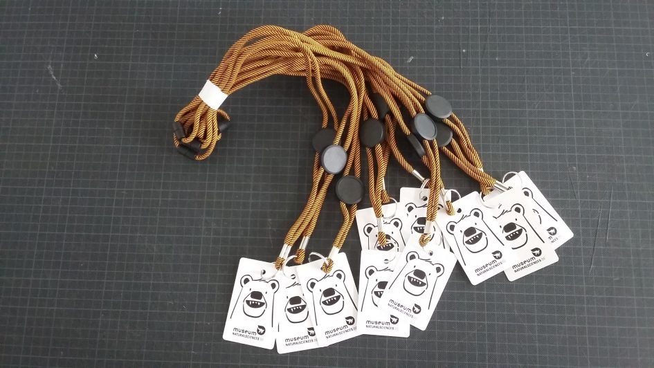
It all started when the team of the Royal Belgian Institute of Natural Sciences decided to base their new “Teddy & Bears” exhibition on RFID tags being used by visitors to enjoy a more interactive visit. The rfid tags would be used to triggers various videos, sounds, lights… depending on visitor actions and targeted to their correct language.
Radio-frequency identification (RFID) uses electromagnetic fields to automatically identify and track tags attached to objects. The tags contain electronically-stored information. Passive tags collect energy from a nearby RFID reader’s interrogating radio waves. Active tags have a local power source (such as a battery) and may operate hundreds of meters from the RFID reader. Unlike a barcode, the tag need not be within the line of sight of the reader, so it may be embedded in the tracked object. RFID is one method for Automatic Identification and Data Capture (AIDC)
wikipedia
Since we (Julien Leresteux and I) had experience designing and teaching arduino and raspberry projects at the Fablab’ke (a Fablab dedicated to kids), we decided to make a proposal for the Museum.
Prototyping phase
An extensive week of research started. The goal was to build a minimum viable product that would reliably trigger a video file when an RFID tag was presented.
I decided to separate the problem in two parts :
- rfid and automation control : Arduino
- video and media playback : Raspberry
…with a usb serial connection between the two. The idea was to reuse as much as possible existing hardware, and produce the minimum amount of custom boards & connectors.
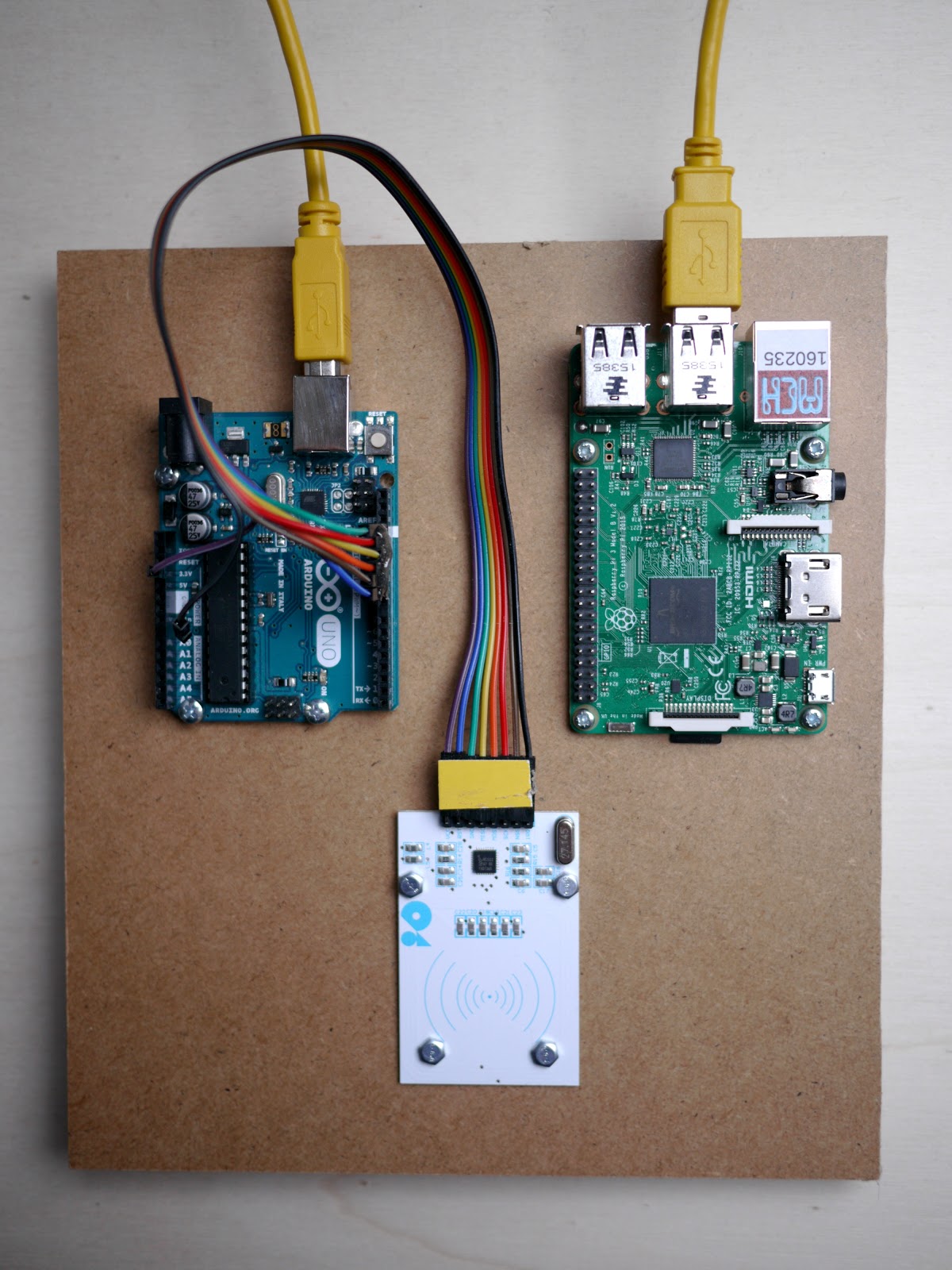
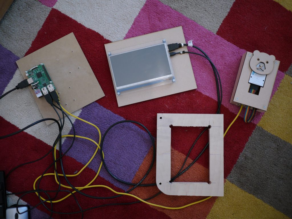
After a lot of research, I had a working prototype that was presented at the museum to validate the concept. Since an uncommon screen size was chosen (7 inches), I also developed a simple enclosure for the screen, using thick 5mm plexiglass protection (this exhibition is intended for kids after all).
The exhibition has 64 rfid readers connected each to an arduino. That itself leads to a lot of wiring. Each arduino is then either left stand-alone with a separate power supply, or connected to a raspberry.
In order to simplify arduino programming, a common library aptly named “bearlib” was developed. It contains all the RFID high level function we need and exclusively used on this project. The existing RFID library we used works really well, but is hard to understand. With our library it all became a matter of using a few functions like bear_set_locale() / if (bear_has_card()) / etc…
Note that the code for the 64 arduino is also on GitHub, to ease collaboration, and to avoid trouble later when we’ll have to re-program some of the arduino in case of failure.
There are 24 raspberry each with an hdmi screen and/or audio. The raspberry was itself a big challenge : we’d need to have a bullet proof solution to play video files, have instant playback and perfect looping of video files. The raspberry are shut down each day, without warning. This is supposedly a receipt for disaster if nothing is done to prevent SD card failure. To avoid troubles the following was done :
- use a read only root filesystem with an overlayed read/write filesystem stored in ram
- use the same raspberry image for all devices, letting the arduino decide what to show
- store the media on a separate usb key that can easily be replaced in case of problem
- put everything on GitHub for posterity and future enhancements : the player code is here.
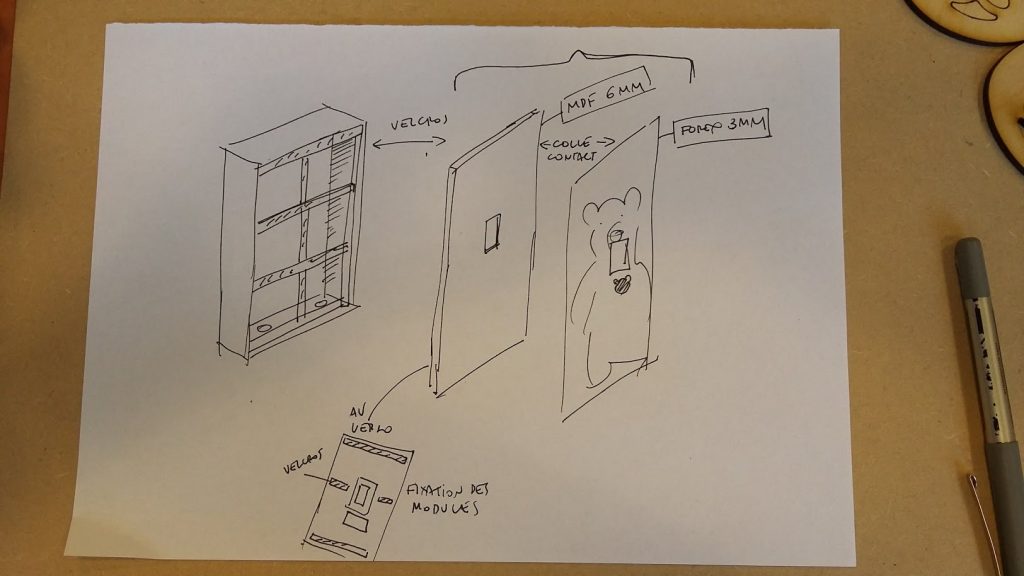
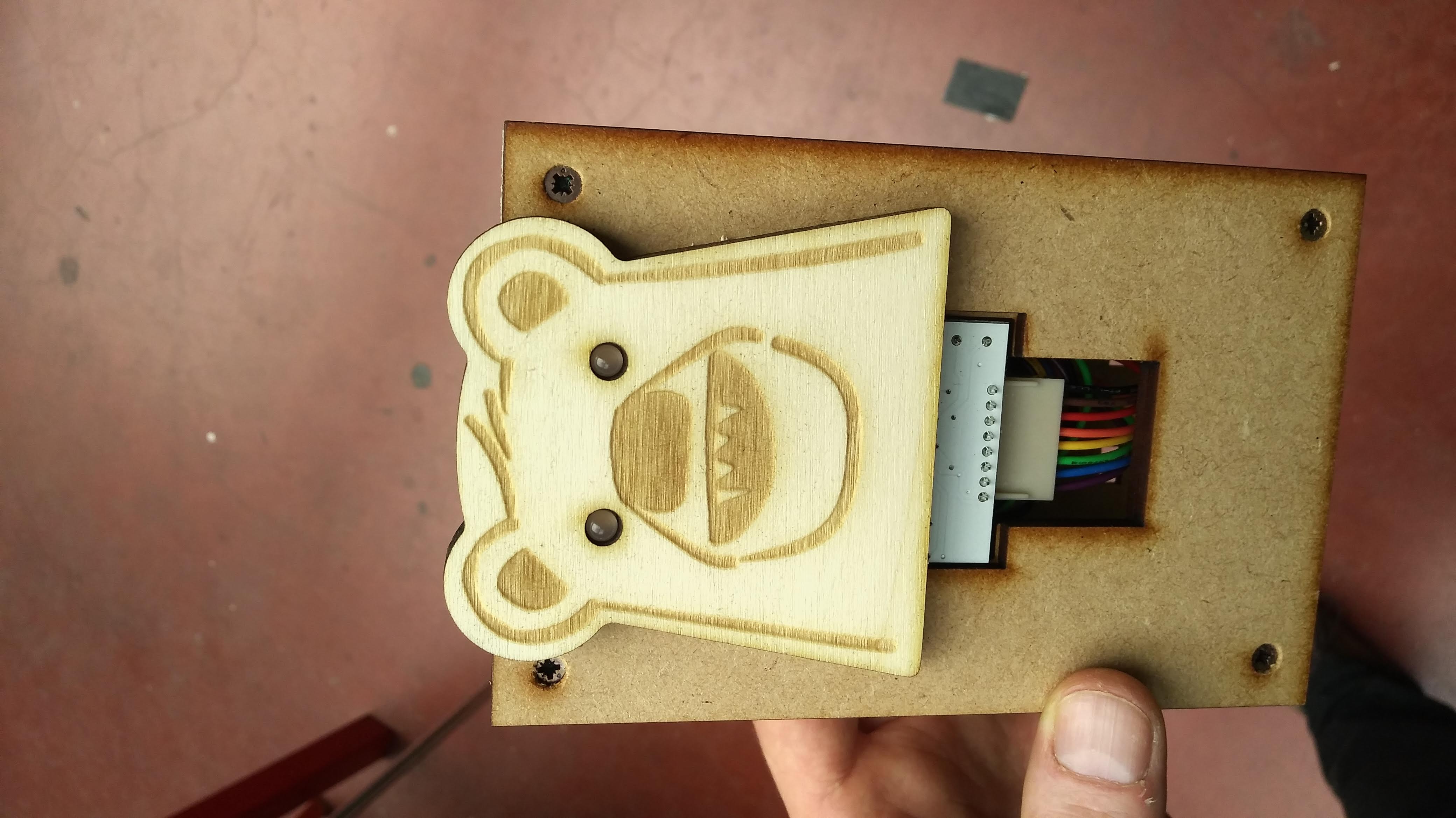
After working on software, it was time to develop a simple enclosure system. We have access to a laser cutter @ microfactory and Julien taught me how to use Fusion 360, a 3d cad tool that proved perfect for the job.
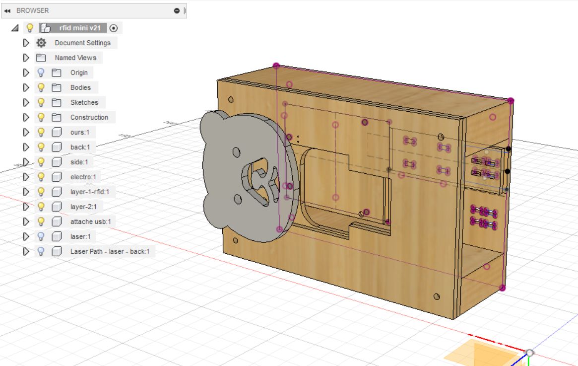
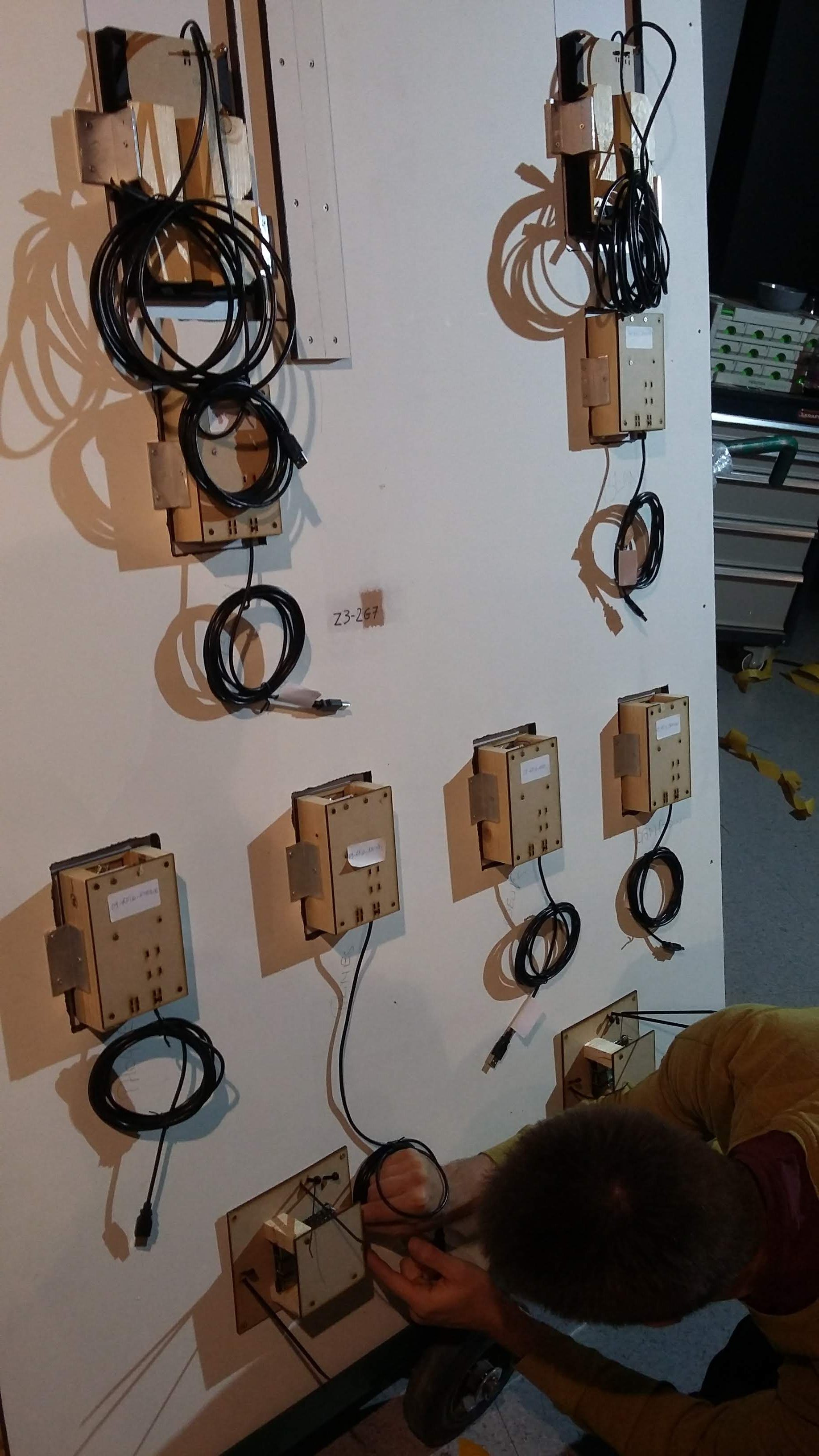
I built several prototypes of enclosures holding the arduino and the rfid reader in a wooden box, ready to be installed behind a forex print by the museum technical team. The design goal was to put the rfid reader as near as possible to the front, to extend the radio reading for visitors. The two large wooden blocks make it easy to screw the module anywhere in the exhibition.
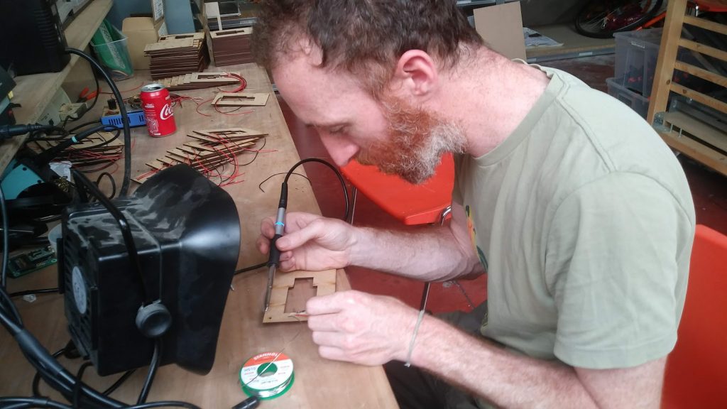
“Mass” production
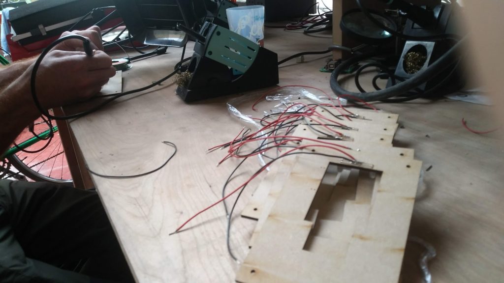
With 64 modules to produce, we really had to be efficient on the soldering front. Instead of making our own pcb’s we used of the shelf prototyping shields for arduinos. It made it very easy to connect the rfid pcb using short cables (the SPI protocol used doesn’t like too much length), add two leds that are the bear’s eyes, and a few resistors.
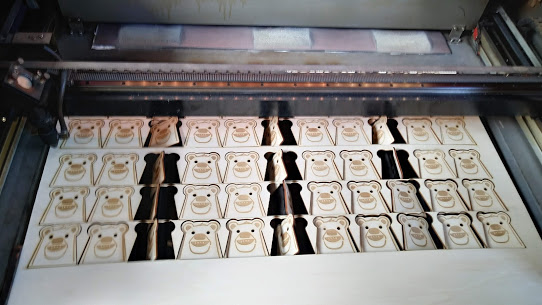
Laser cutting the bears
All in all a very repetitive process that took much longer than anticipated. Hardware is hard as they say.
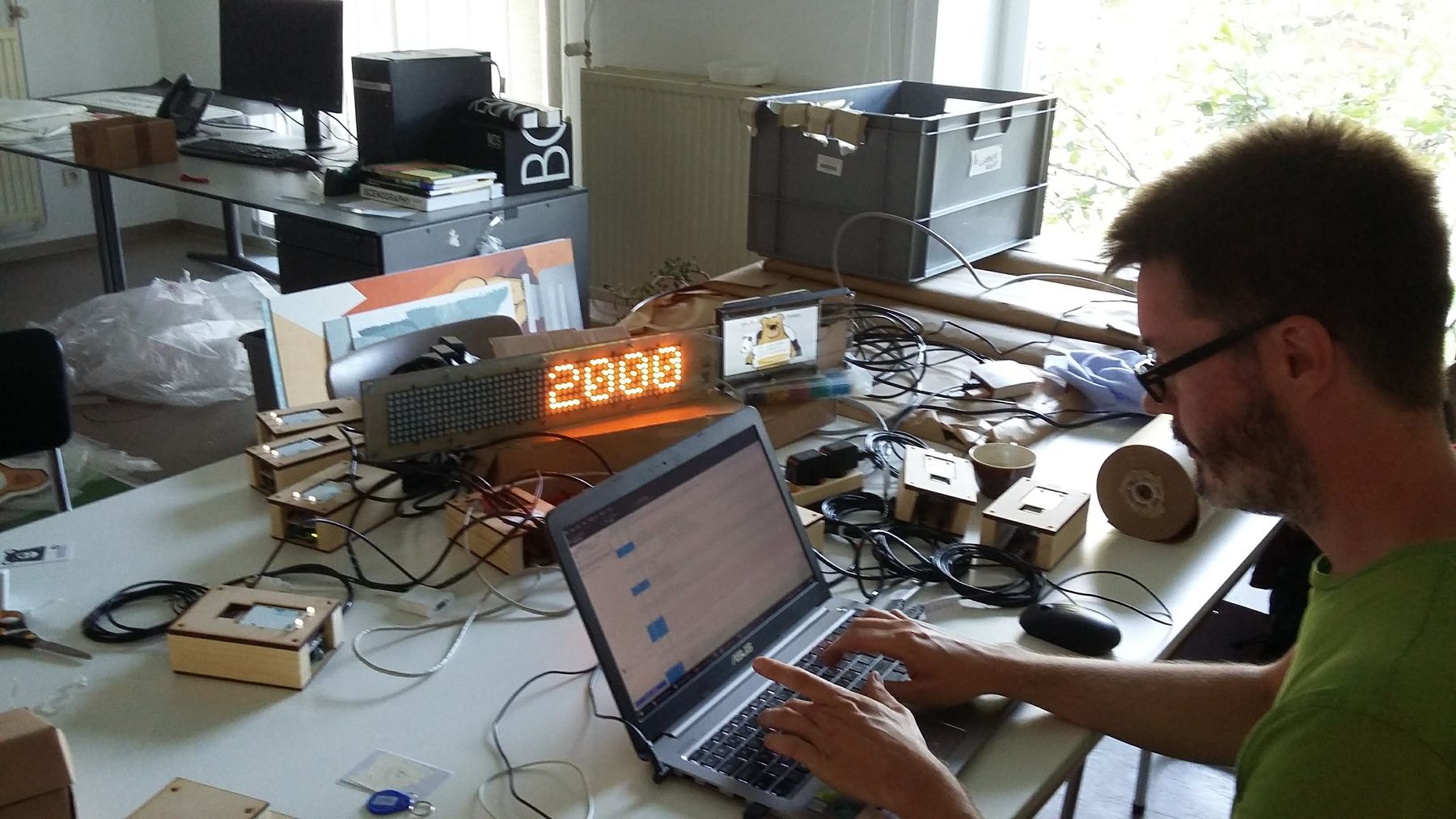
Installing it all & stress test
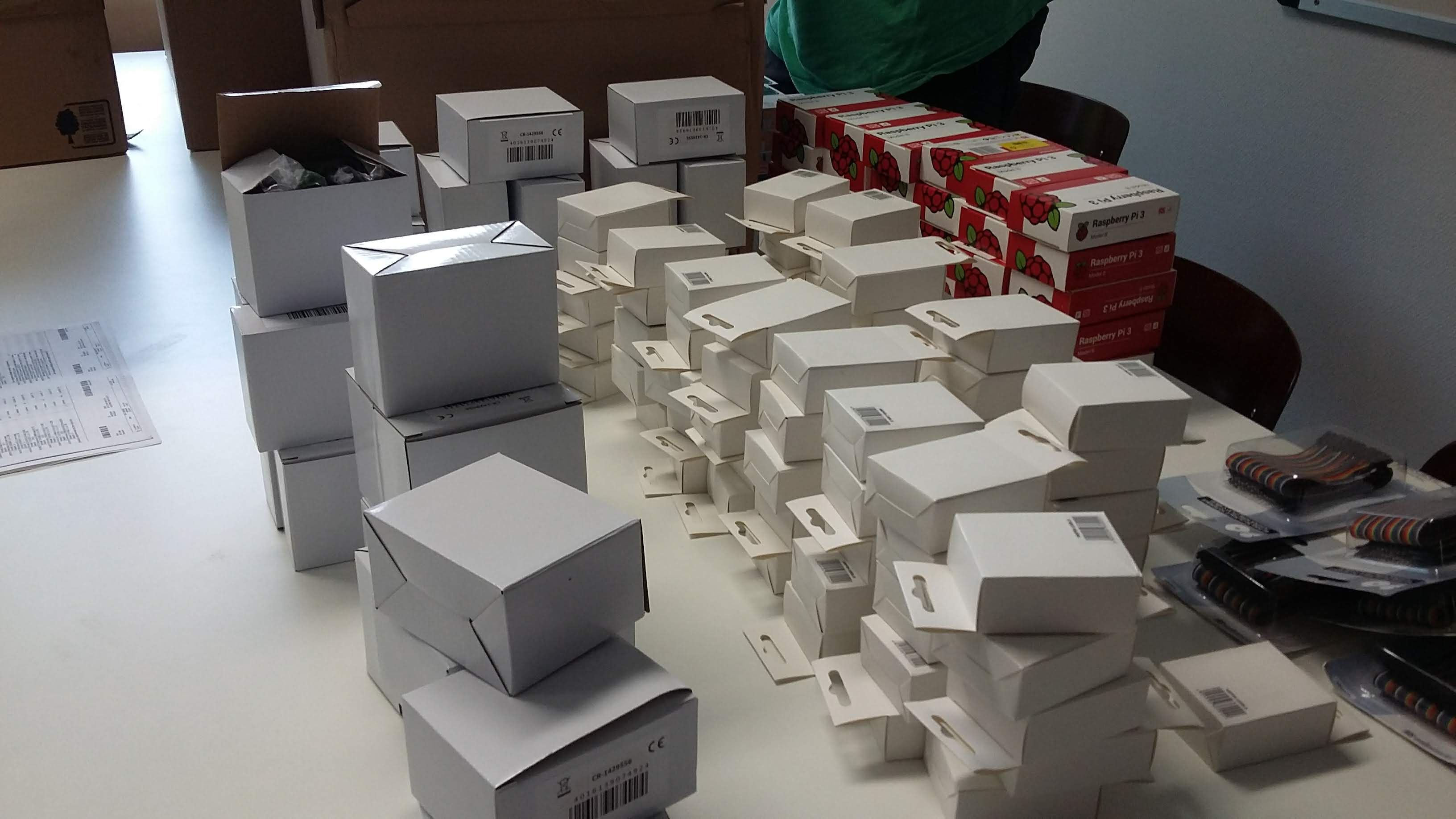
Three weeks before the opening, we started working on the installation of all the modules. The technical team of the museum made a great job of putting it all together. We had sorted everything in boxes (one per project) to make our life easier. Most connections were made with of the shelf usb and hdmi cables leaving little room for error.
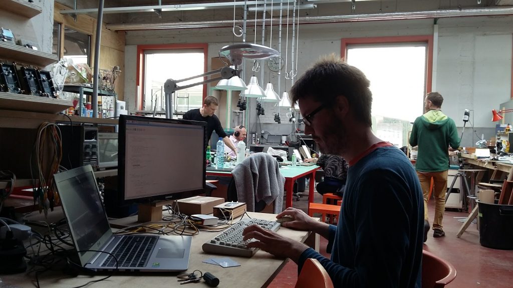
Then it was time for debugging and testing in the real context of the exhibition. A lot of debugging happened at this stage, because some subtle timing issues appeared, which were only fixable during the installation.
Opening
I learned that the night before any opening involving electronic/computer equipment, one will sleep badly. The exhibition opened the 18 October 2018 and all went well. The public received very positively the rfid concept developed by the museum team and our little machines worked almost flawlessly.
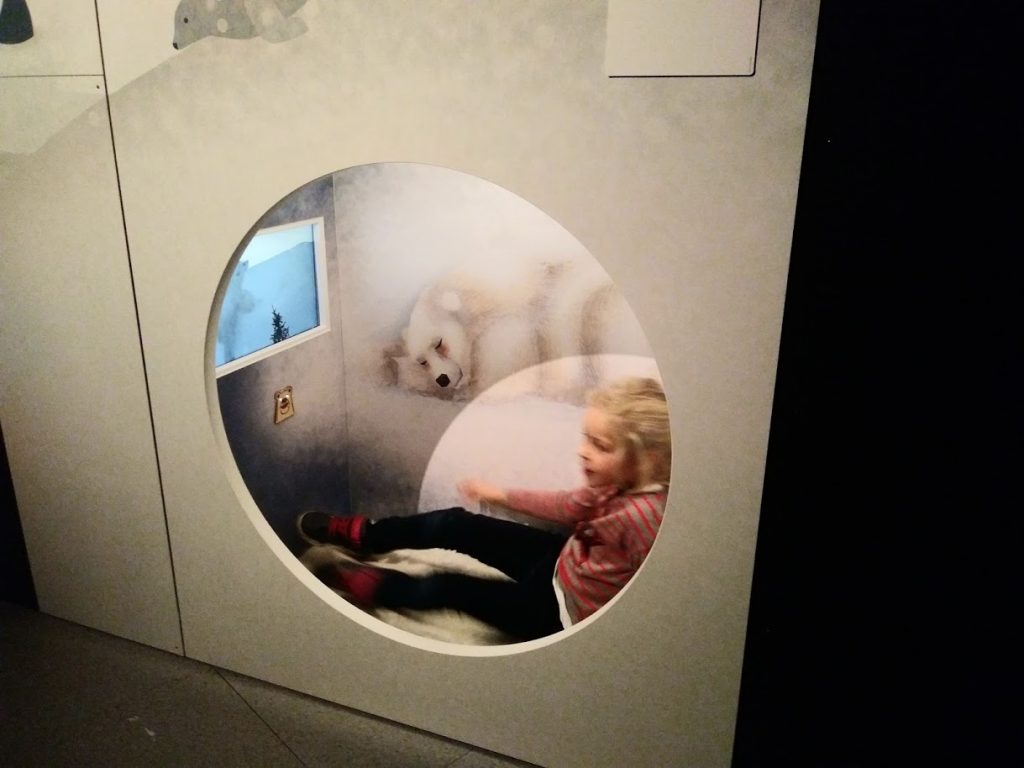
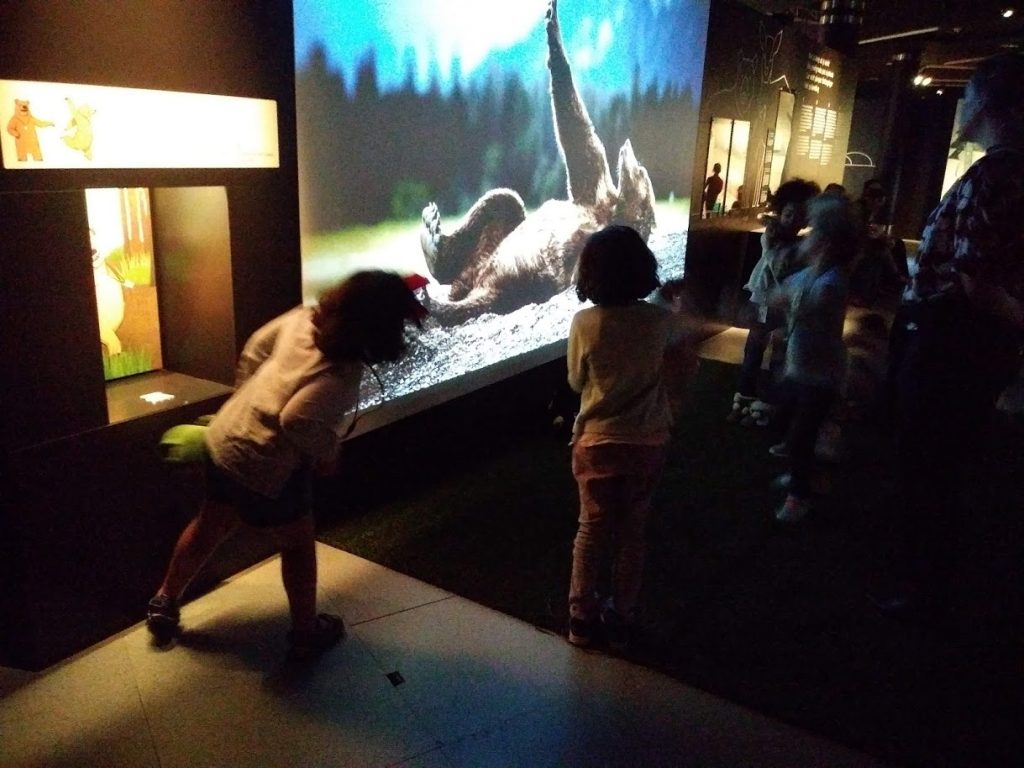
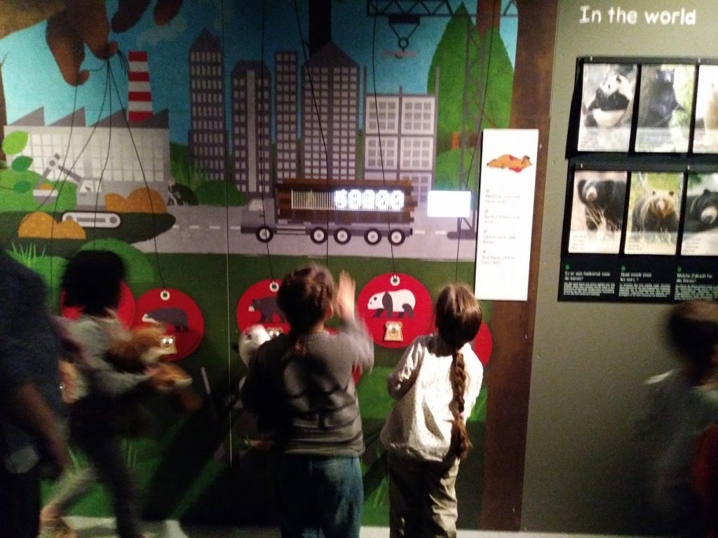
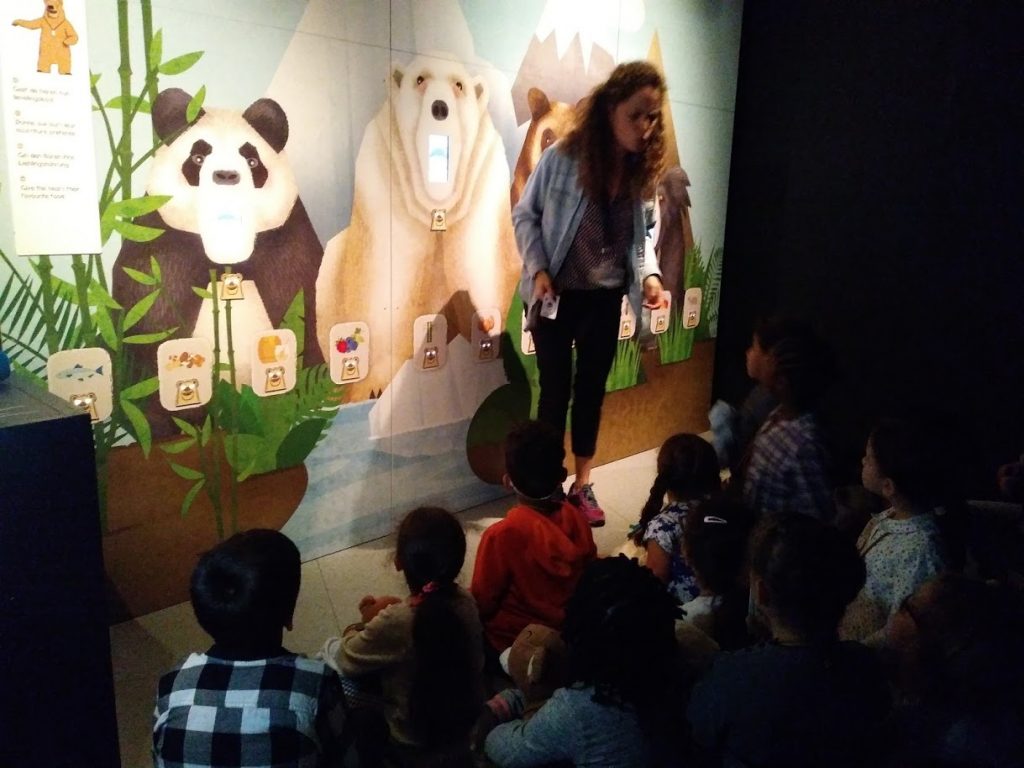
First little visitors
Issues and problem mitigation
We experienced weird startup problems on random raspberries, but suspected a general power issue in the museum.
We installed a power quality line meter and found a lot of weird issues (power spikes, swells and grounding issues). The problems were even more strange with arduino hanging randmoly, but only during the installation. We suspect electrical noise on the lines created by the large wood saw and equipment being used during this period.
To reduce the risks of failure several changes were made :
- Simplify the raspberry payload (boot to cli instead of gui). Use systemd to monitor the process and start everything in the right order (we went from a 5 gb image to 2gb which is still huge. Boot time decreased from 40 to 20 seconds).
- Install simple restart switch at strategical points in the exhibition to allow museum staff to reboot hanged points during the day. Downtime is very low ~20 seconds.
Conclusion and future projects
All in all this was a really interesting ride. We’d like to thank the Museum staff : first because they trusted us, second because they helped us tremendously and gave all the required information/content in time. I know from the website publishing world that often you build a lot of machinery to discover later that client is not using it or not putting the content in time, creating a huge stressful bottleneck. That was clearly not the case here. The big preparation phase was made especially to avoid stress later in the process. It clearly paid.
We are open for other rfid/arduino/raspberry/video/audio related projects. I see a nice pattern here where we teach kids at the Fablabke how to build stuff and re-use almost the same technology in a professional context (dare I say mission critical? :-)). I’ll sure report of our other experiments and projects here.